

SERVICES | FORMING & PRESS BRAKE
Forming & Press Brake
Press brake forming for drawing-driven parts — brackets, channels, flanges, and enclosure components — formed in-house from our own laser- and waterjet-cut blanks and carried straight into welding, machining, and inspection.

What This Process Is Built For
Forming is rarely the whole job. Most formed parts at UWF start as flat blanks from our laser or waterjet, get bent to print on our press brakes, and then move into welding, machining, or assembly without leaving the building. That matters when bend geometry has to line up with machined features or weld fit-up: the same drawing, revision, and inspection expectations follow the part through every step.
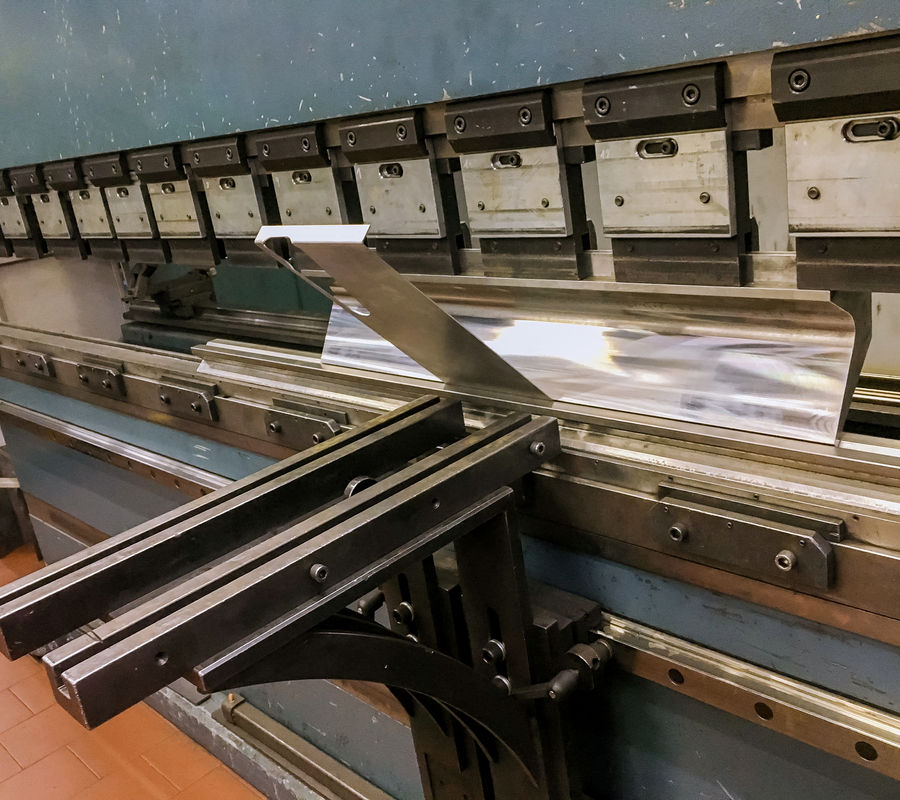
We form parts sized to our brakes and handling — up to 8 ft in length — in mild steel, stainless, and aluminum. All forming is done in-house in Ham Lake, Minnesota.
Capacity & Handling
-
Press brakes up to 8 ft bed length, 60-ton and 100-ton range
-
Shear, saws, tube-fabrication and fab support equipment
-
Blanks cut in-house on our fiber laser (approx. 10' × 5') or waterjet (approx. 13' × 6.5')
We focus on parts that can be formed safely and accurately within this range. If a part exceeds our bed length or tonnage, we’ll say so at quoting rather than force it.
Materials We Form
-
Mild steel
-
Stainless steel
-
Aluminum
Material, thickness, and grain direction all affect bend radius, springback, and the risk of cracking on the outside of the bend. Tell us the material spec and thickness on the RFQ and we’ll confirm the forming approach before quoting. For wear-resistant or hardened plate, ask — bendability is limited and we’d rather confirm than assume.
Forming Requirements & Tolerance Review
Formed-part requirements depend on material, geometry, tooling, bend location, and the drawing requirements for the finished part. During quoting, we review items such as inside bend radius, flange references, supplied flat-pattern assumptions, hole-to-bend clearances, cosmetic faces, and downstream operations that can affect the forming plan. Requirements are confirmed against the drawing before production rather than treated as a universal shop tolerance.
Bend Design for Manufacturability
-
Minimum flange length for the tooling required by the bend radius and material thickness
-
Bend sequence and tool clearance on box-shaped or multi-bend parts
-
Bend relief at intersecting bends
-
Feature placement relative to bend lines
-
Whether a formed part is better made as a weldment, or vice versa
A short DFM review before material is cut saves rework at the brake. If we see a manufacturability issue we’ll raise it with the quote, not after the parts are bent.
Typical Parts
-
Brackets and formed tabs
-
Channels and angles
-
Flanges and stiffeners
-
Guards, covers, and enclosure panels
-
Formed parts that go into weldments and assemblies
-
Components that will be machined or welded after forming
Integrated With Other Processes
Most formed parts begin as flat blanks from laser cutting or waterjet cutting and then move into welding and fabrication for final assembly.
For the fastest and most accurate quote, send the drawing or model, revision, material and thickness, quantity, and any bend-radius, angle, or flatness requirements. If you supply a flat pattern, tell us the bend allowance or K-factor you used.